Capacitors in Parallel
Capacitors store charge on their plates
Capacitors in parallel can be replaced with an equivalent capacitor

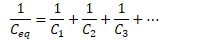
Capacitors in Series
Charge on capacitors must be the same
Capacitors in series replaced with an equivalent capacitor
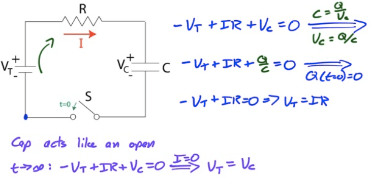
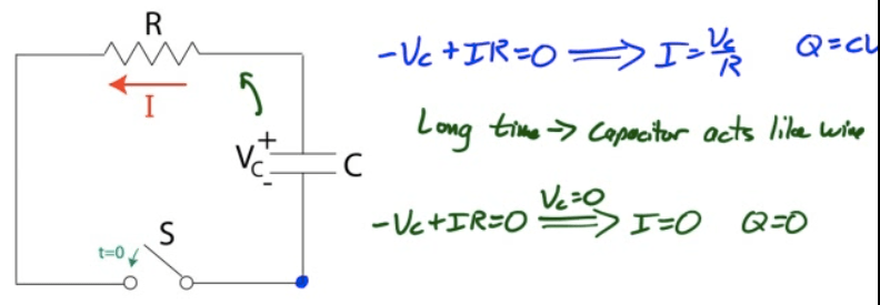
RC Circuits
RC Circuits are circuits comprised of a source of potential difference, a resistor network, and one or more capacitors
We will look at RC circuits from the steady-state perspective
What happens when first turned on
What happens after a "long" time has elapsed
Key to understanding RC Circuit Performance
Uncharged capacitors act like wires
Charged capacitors act like opens
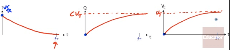
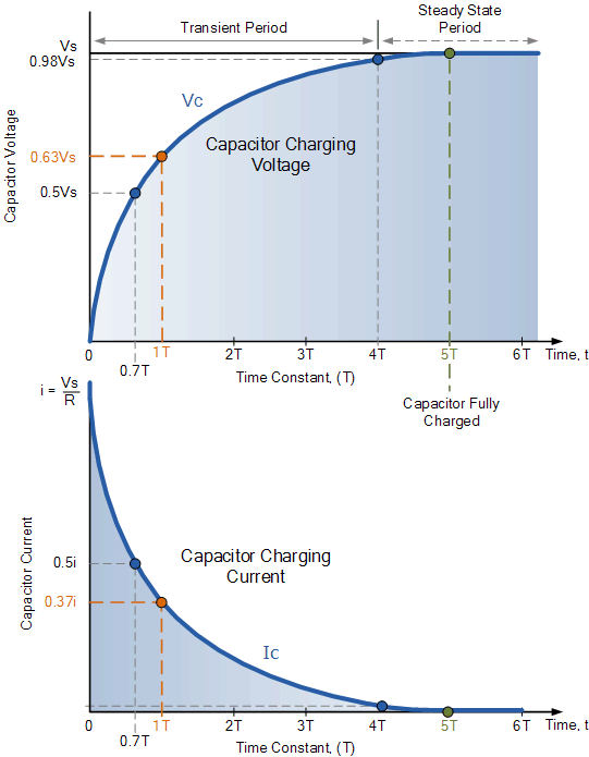
Charging an RC Circuit
Discharging an RC Circuit
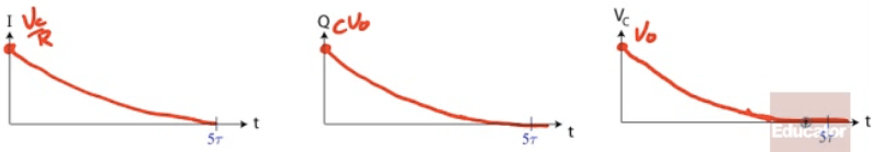
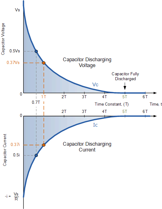
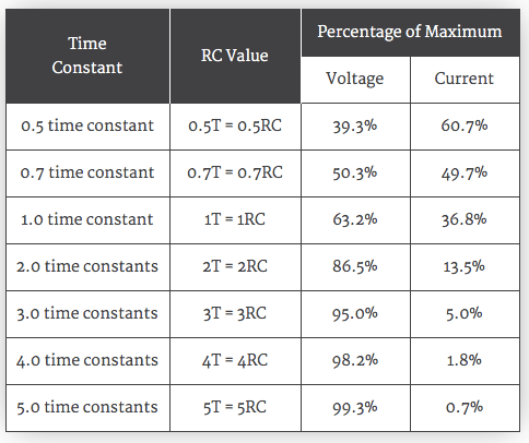
The Time Constant


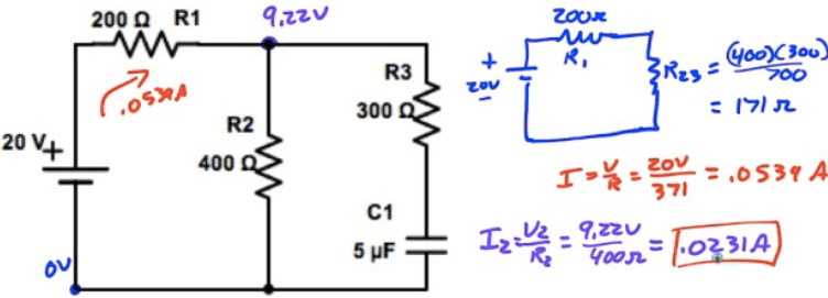
Example 1: RC Analysis
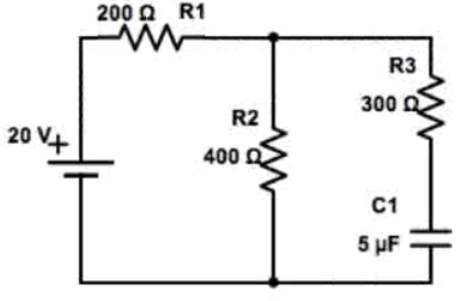
What is the current through R2 when the circuit is first connected?
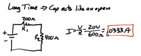
What is the current through R2 a long time after the circuit has been connected?
Example 2: More RC Analysis
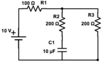
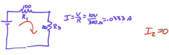
What is the current through R3 when the circuit is first connected?
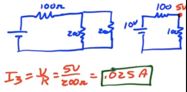
What is the current through R2 a long time after the circuit has been connected
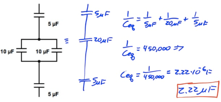
Example 3: Equivalent Capacitance
What is the equivalent capacitance of the capacitor network shown below?
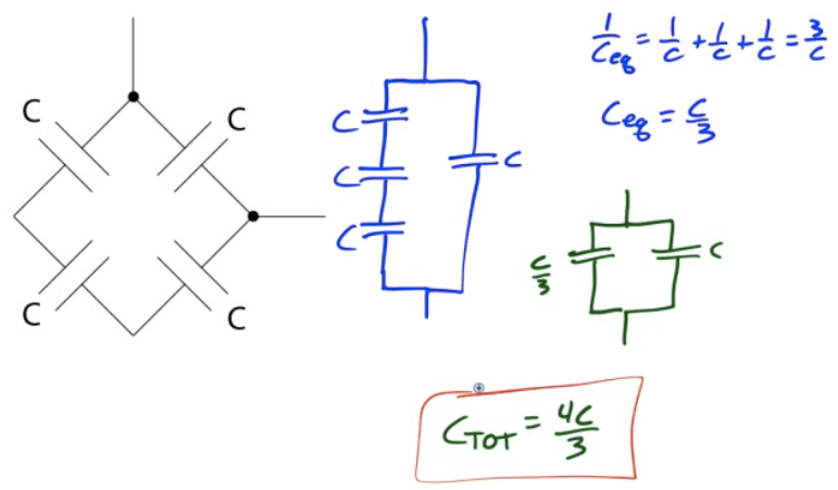
Example 4: More Equivalent Capacitance
What is the equivalent capacitance of the capacitor network shown below?
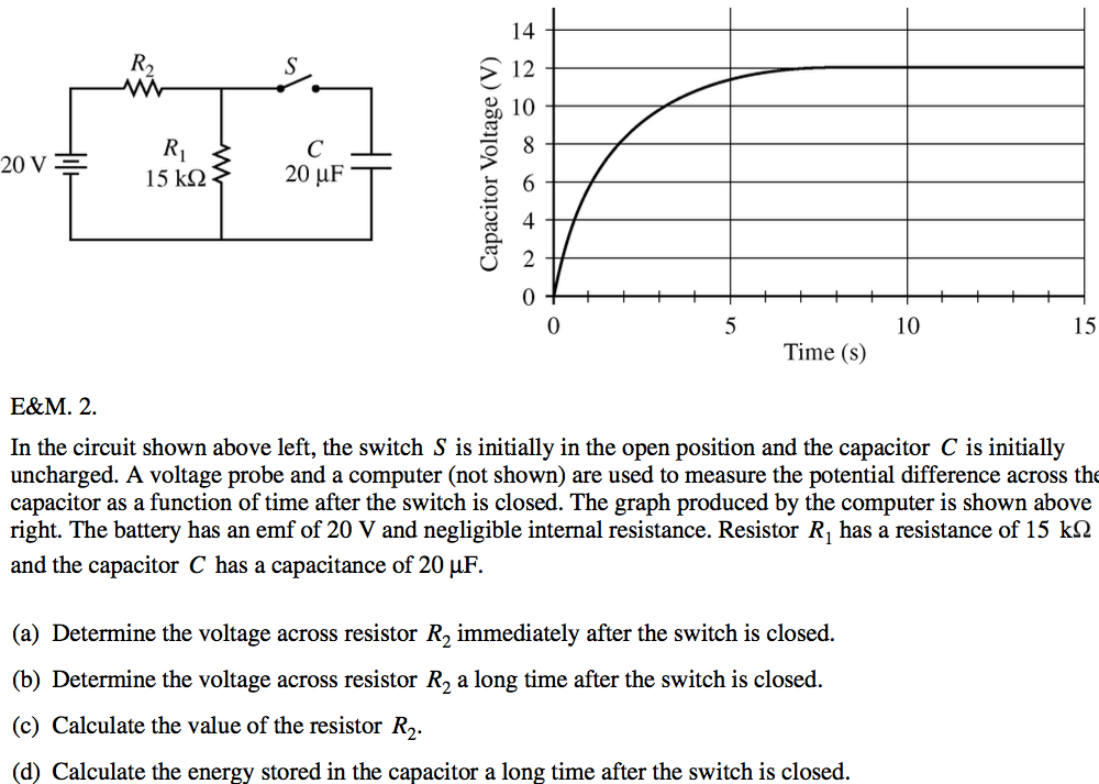
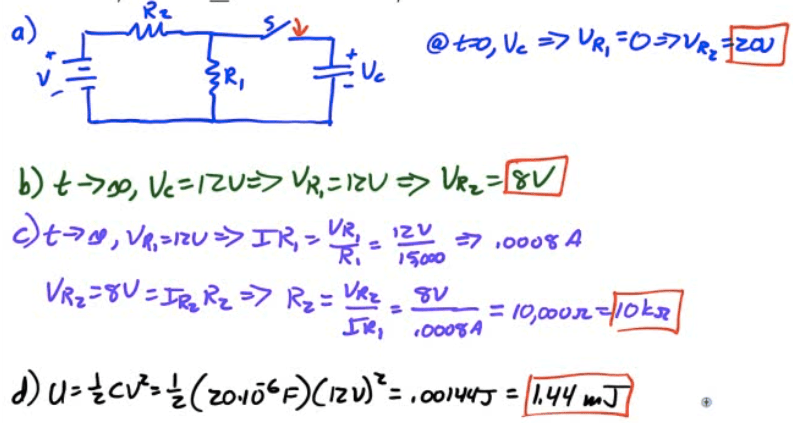
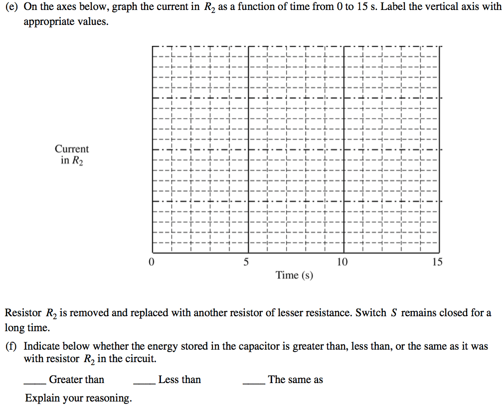
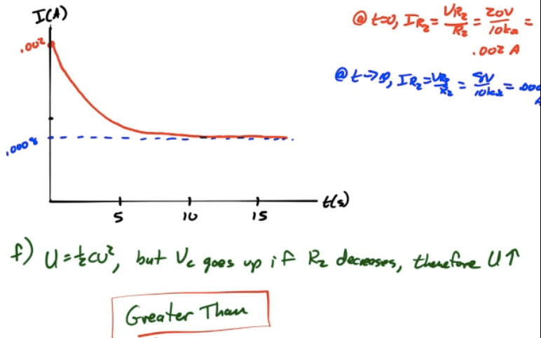
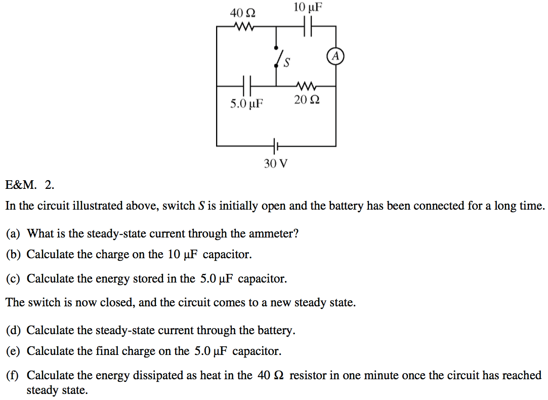
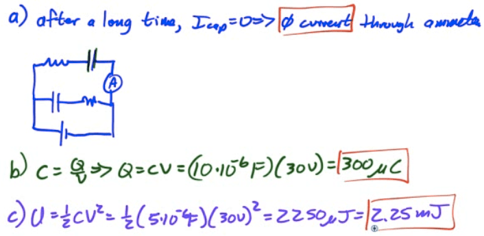
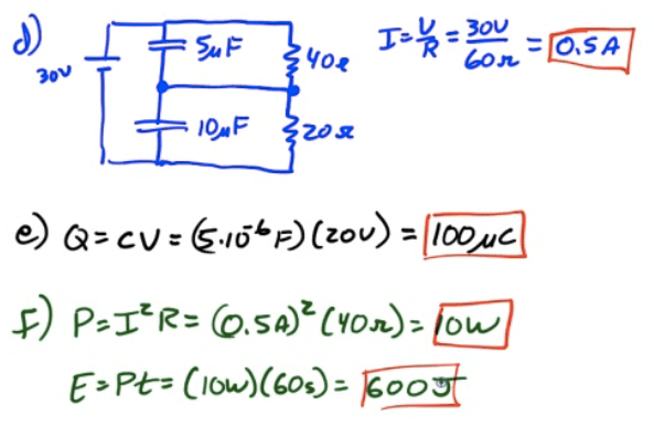
2010 Free Response Question 2
2004 Free Response Question 2