Introduction
Notes
1. Electricity
1.1 Electric Charge & Coulomb's Law
1.2 Electric Fields
1.3 Gauss's Law
1.4 Electric Potential & Electric Potential Energy
1.5 Electric Potential Due to Continuous Charge Distributions
1.6 Conductors
1.7 Capacitors
2. Current Electricity
2.1 Current & Resistance
2.2 Circuits I: Series Circuits
2.3 Circuits II: Parallel Circuits
2.4 RC Circuits: Steady State
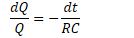
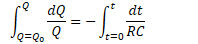
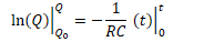
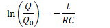
2.5 RC Circuits: Transient Analysis
3. Magnetism
3.1 Magnets
3.2 Moving Charges In Magnetic Fields
3.3 Forces on Current-Carrying Wires
3.4 Magnetic Fields Due to Current-Carrying Wires
3.5 The Biot-Savart Law
3.6 Ampere's Law
3.7 Magnetic Flux
3.8 Faraday's Law & Lenz's Law
4. Inductance, RL Circuits, and LC Circuits
4.1 Inductance
4.2 RL Circuits
4.3 LC Circuits
5. Maxwell's Equations
5.1 Maxwell's Equations
Problem Set
1998 Multiple Choice
2004 Multiple Choice
2009 Multiple Choice
Practice Exam Multiple Choice
Princeton 1 Multiple Choice
Princeton 2 Multiple Choice
Sample Questions
Published with GitBook
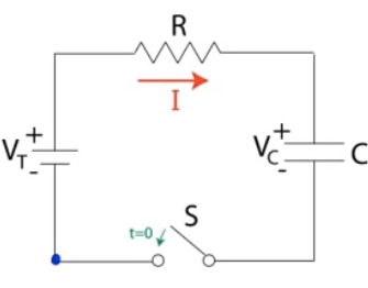
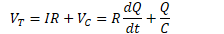
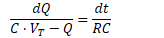
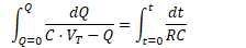
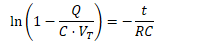
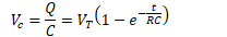
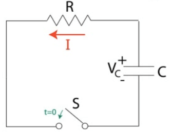
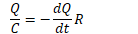
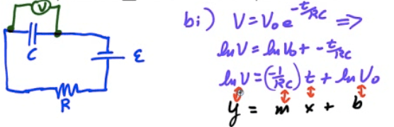
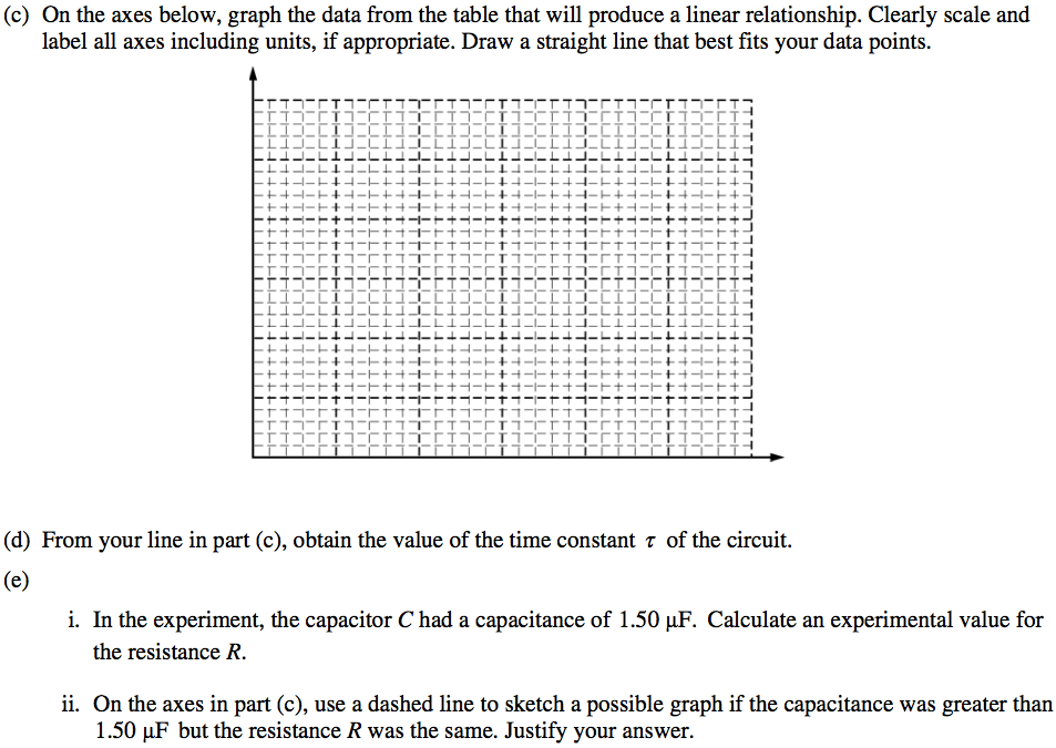
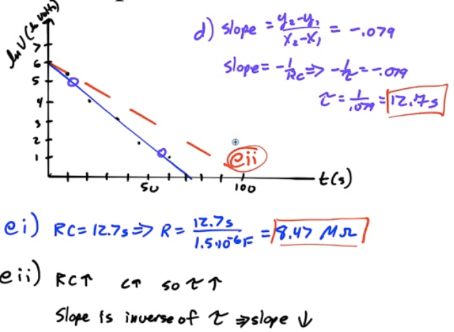
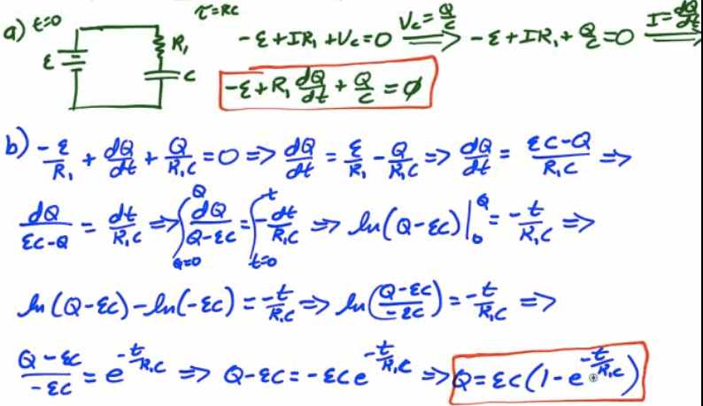
2.5 RC Circuits: Transient Analysis
Charging an RC Circuit
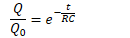
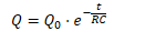
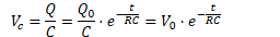
Discharging an RC Circuit
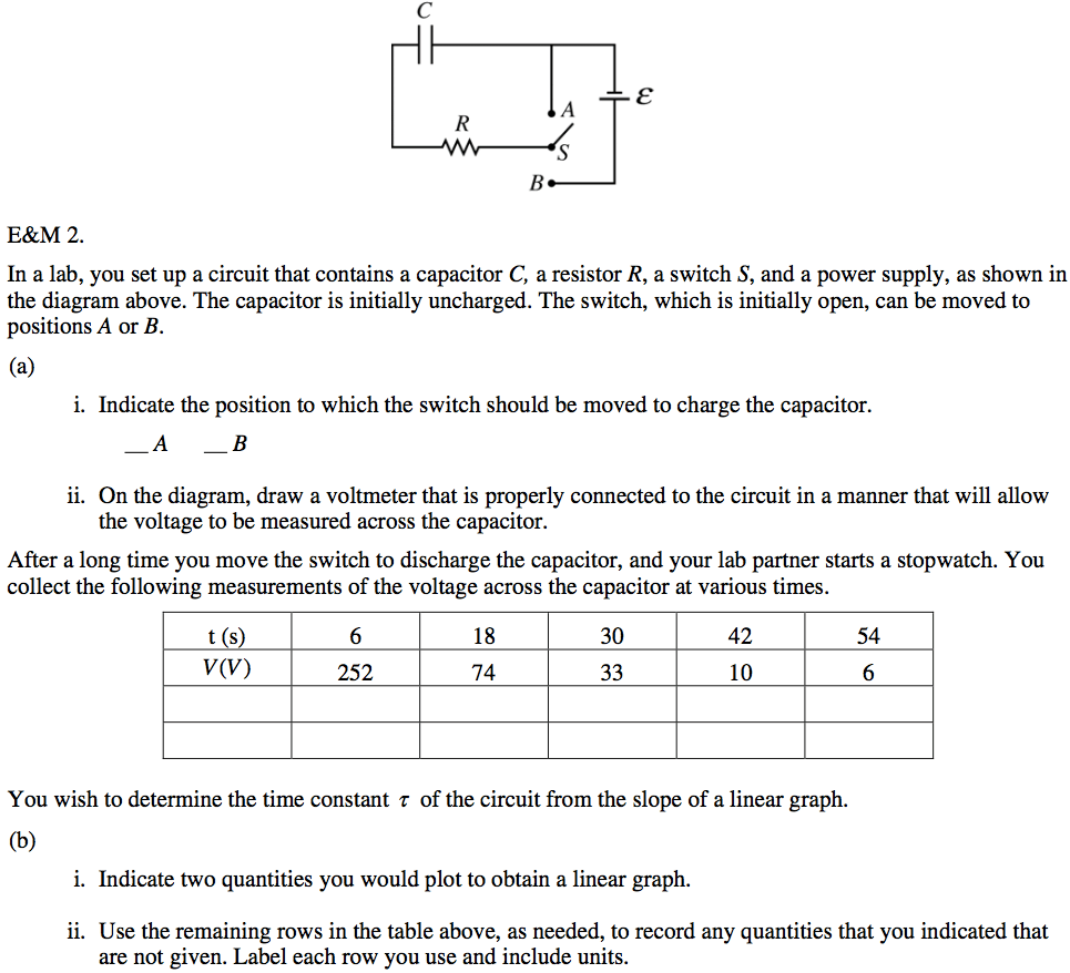
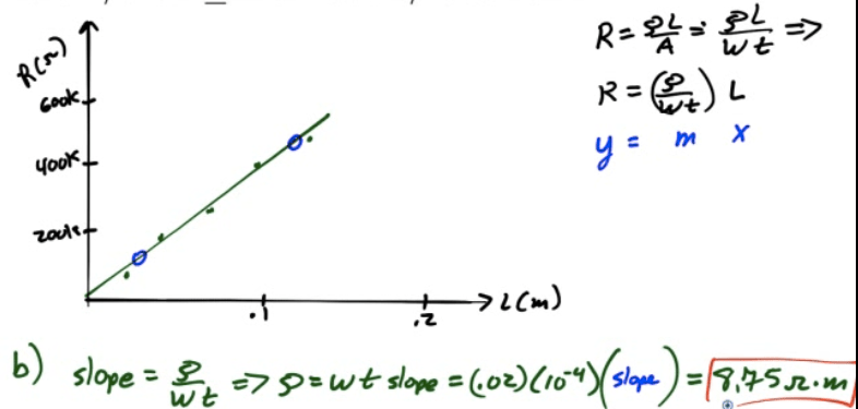
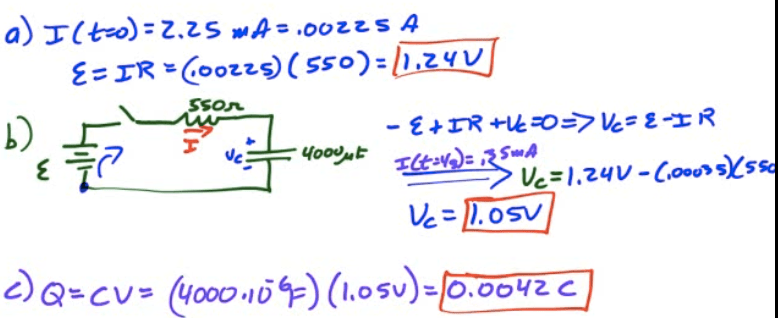
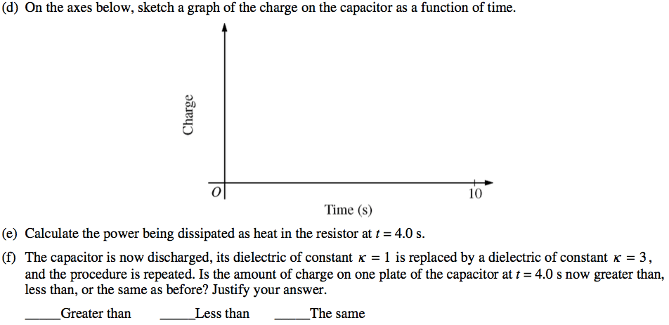
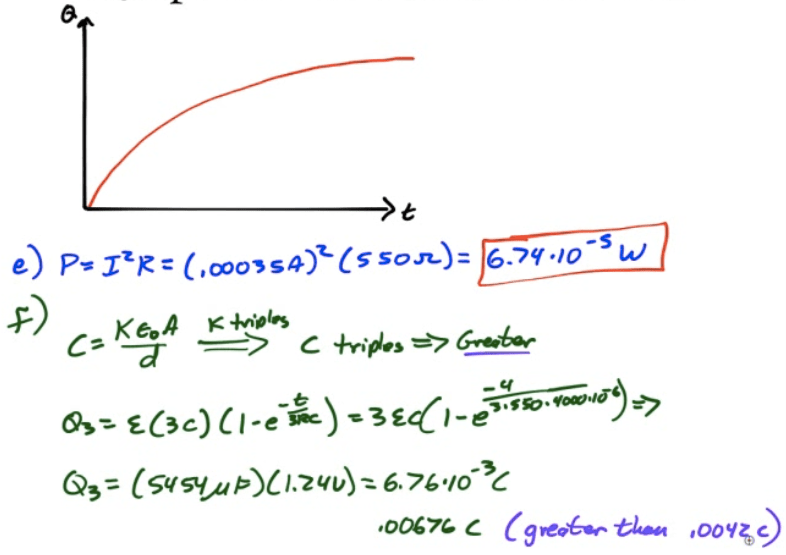
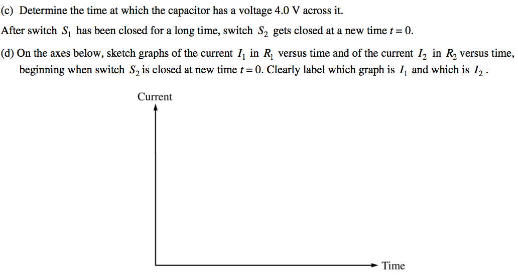
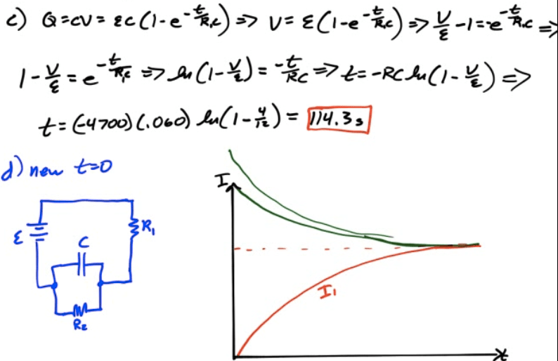
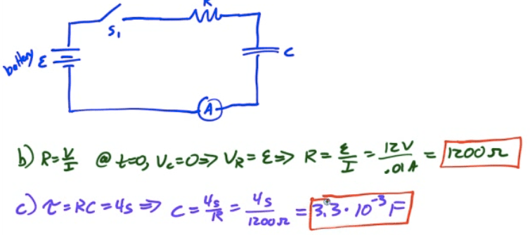
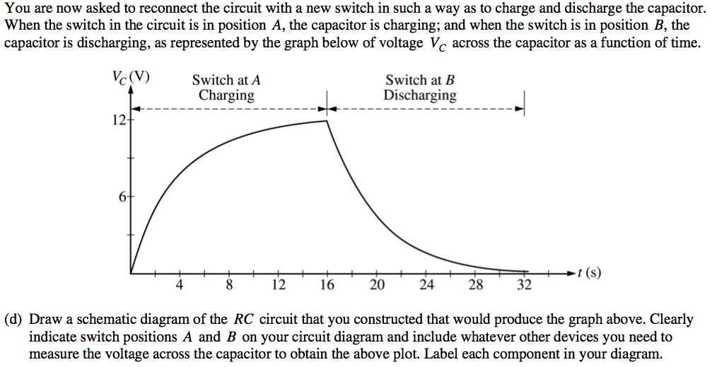
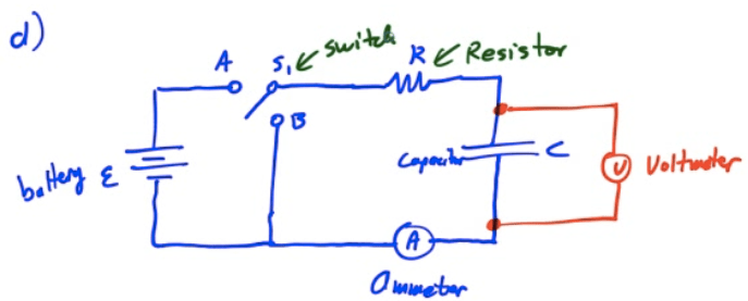
2013 Free Response Question 2
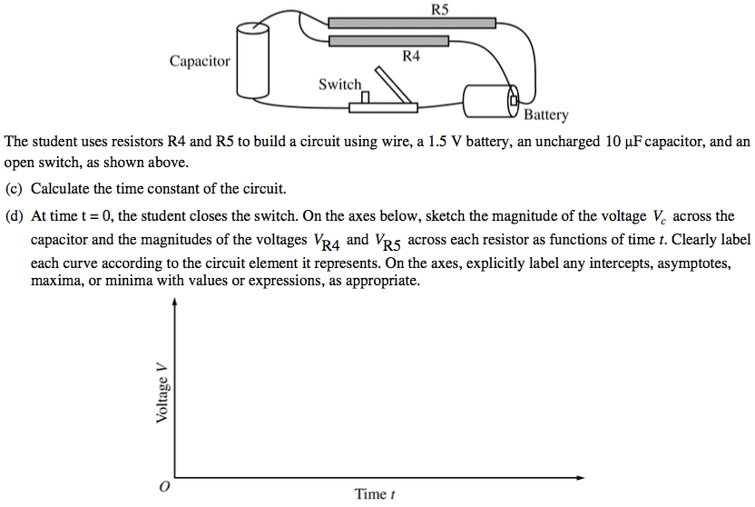
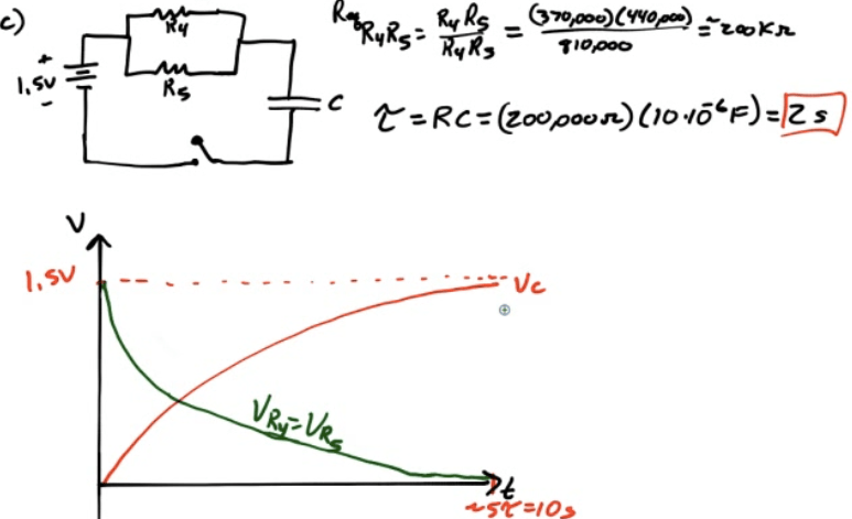
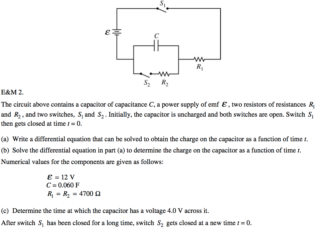
2012 Free Response Question 2
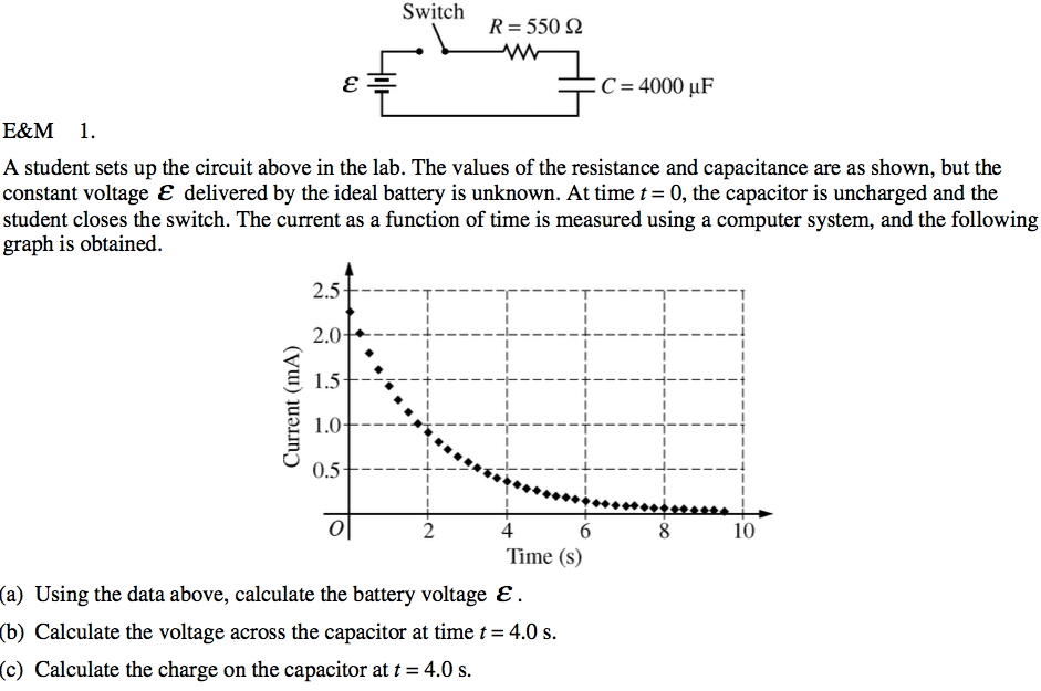
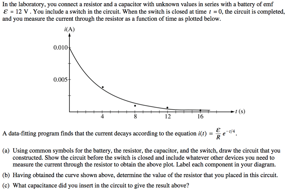
2007 Free Response Question 1
2006 Free Response Question 2
2003 Response Question 2
results matching "
"
No results matching "
"